1. Core Concepts and Process Mechanics
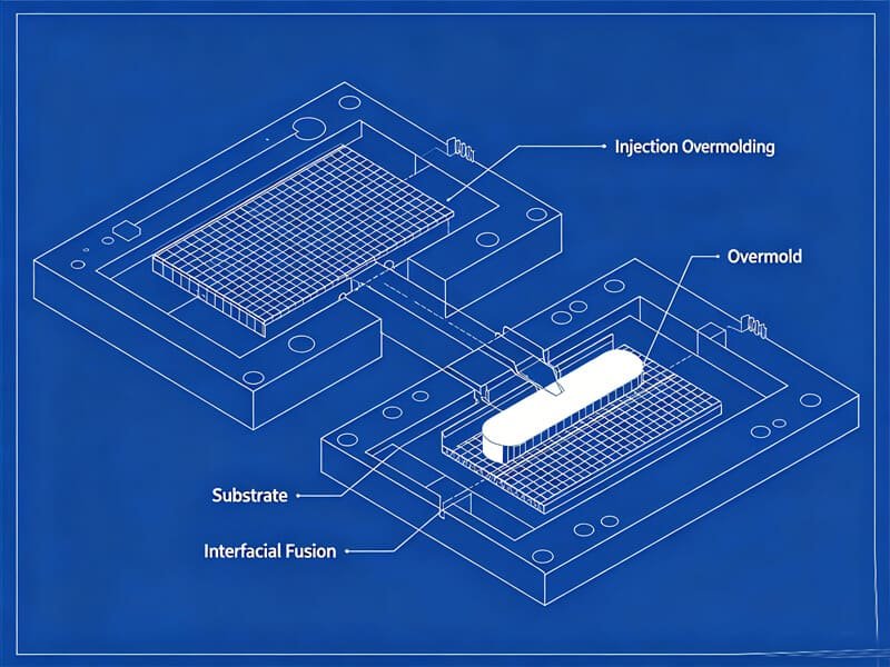
Overmolding is a custom injection molding process that merges multiple materials into a single, cohesive component. This process typically utilizes a rigid substrate as the structural foundation, which is then overlaid with a secondary material layer—often a soft, rubber-like thermoplastic elastomer (TPE) or thermoplastic polyurethane (TPU). Rather than relying on separate parts that require post-molding assembly, overmolding accomplishes the integration directly inside the mold tooling, resulting in a single part with varied textures, colors, and physical properties.
The overmolding workflow generally consists of two key stages. First, the substrate is molded using traditional injection molding techniques and allowed to cool. The substrate can be made of various rigid materials, including engineering plastics like polycarbonate or ABS, or non-plastic components like metals, glass, or circuit boards. In the second stage, the substrate is positioned inside the overmold cavity. The overmold material is then injected directly over, through, or around the substrate. As the secondary material cools and solidifies, it forms a mechanical or chemical bond with the substrate, resulting in a single, robust part.
“Overmolding allows product developers to combine the structural strength of rigid plastics with the tactile, ergonomic benefits of soft elastomers without resorting to manual assembly.”
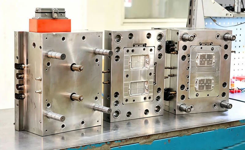
To successfully execute this process, machinery selection is a vital consideration. Overmolding can be performed on both horizontal and vertical clamp injection molding machines. Vertical clamp machines are particularly well-suited for insert overmolding. Because the bottom mold half remains stationary and opens upward, gravity naturally holds preformed metal inserts, circuit boards, or plastic substrates securely in place during the mold-closing and injection stages. This reduces the risk of part displacement and ensures repeatable alignment across high-volume production runs.
| Manufacturing Feature | Standard Injection Molding | Overmolding Process (2K / Insert) |
|---|---|---|
| Material Complexity | Single polymer or elastomer per cycle | Two or more materials merged in a single part |
| Secondary Assembly | Required for multi-material parts | Completely eliminated; occurs within the mold |
| Initial Tooling Cost | Lower upfront investment | Higher tooling cost due to complex cavities |
| Bonding Integrity | N/A | Provides molecular fusion or mechanical locks |
| Common Applications | Single-color housings, structural brackets | Ergonomic handles, sealed enclosures, button arrays |
In addition to standard thermoplastic overmolding, liquid silicone rubber (LSR) overmolding is becoming the preferred manufacturing process across a range of industries, including healthcare and automotive. Liquid silicone rubber provides unique properties such as thermal stability, flexible design opportunities, and chemical inertness. When molding LSR onto a thermoplastic substrate, we must choose a plastic that can withstand the high curing temperatures of silicone (typically 300°F to 400°F). Glass-filled Nylon, PBT, and polyetherimide (PEI) are highly suitable choices for these applications because they maintain their dimensional stability under extreme heat. By overmolding LSR directly onto these rigid backbones, we produce components that benefit from both the structural strength of the plastic and the compression-set resistance of the silicone.
2. Overmolding Taxonomy and Tooling Variations
Depending on production volumes, capital budgets, and design complexity, overmolding is divided into two primary sub-processes: standard (pick-and-place) overmolding and two-shot (multi-shot) overmolding. Both techniques produce high-quality multi-material components, but they diverge significantly in process complexity, tooling requirements, and economic break-even points.
Standard (Pick-and-Place) Overmolding
Standard overmolding, also known as insert overmolding, uses two completely separate molds and distinct molding cycles. First, the substrate parts are molded in Mold A and allowed to cool. These substrate components are then placed, either by hand or with simple pick-and-place automation, into Mold B. The overmolding resin is injected over the substrate, completing the part. This method requires less capital investment, as the tooling is simple and can run on conventional single-shot injection presses. However, because the substrate cools completely before the second shot, the chemical bond is less cohesive compared to automated methods. For this reason, parts are often preheated before the second injection to promote adhesion, and designers commonly incorporate mechanical undercuts to ensure secure retention. Standard overmolding is highly cost-effective for annual production volumes under 250,000 units.
Two-Shot (Multi-Shot / 2K) Overmolding
Two-shot overmolding, or 2K molding, is an automated continuous process carried out on a single injection molding machine equipped with multiple injection units (barrels). The machine molds the substrate, rotates or indexes the mold core, and immediately injects the overmold material before the substrate cools. Because the substrate is still warm, the secondary polymer forms a superior, permanent molecular bond at the interface. The main mechanical tool structures used to facilitate this process include:
- Rotary Platen Molds: The mold core plate rotates 180 degrees (or 120 degrees in 3-shot methods) to align the newly molded substrate with the secondary cavity for the overmold shot. This is highly efficient for symmetric, high-volume parts.
- Core-Back (Movable Core): Uses sliding steel cores that retract after the first injection, creating a cavity space for the secondary material without rotating the mold. It is ideal for linear, non-rotational part designs.
- Seesaw Structures: Uses a pivoting rocker inside the mold to automatically clear passages. This allows the second material to flow into closed, isolated areas of characters or graphics (essential for molding keycaps or buttons with closed loops like ‘0’, ‘A’, ‘B’, ‘O’, or ‘D’).
- Cavity Sliding Structures: The mold cavity slides laterally under motor control to align the first shot with the second injection nozzle, offering high precision for non-symmetric components.
To understand the mechanical complexity of these automated tools, let us take a closer look at the Seesaw Mold Structure. When molding buttons or keyboard caps with closed loops (such as the letter ‘A’ or the number ‘0’), the secondary material cannot easily enter the sealed-off center of the loop. The seesaw structure solves this by using a mechanical pivot. After the first shot is injected, the mold opens, and a push rod lowers a broken needle. This action causes the seesaw to revolve around its rotating shaft, pushing up the top plate. As the top plate rises, the needle creates a small hole at the edge of the sealed-off portion of the primary product. During the second injection, this hole allows the molten elastomer or contrasting plastic to flow through the substrate and fill the closed loop, creating a clean, durable, and highly consistent aesthetic finish. This level of automation ensures high yield rates, but it requires highly precise toolroom capabilities to execute properly.
| Tooling Mechanism | Aesthetic and Design Complexity | Tooling Cost | Volume Fit | Typical Applications |
|---|---|---|---|---|
| Rotary Platen (180°) | High (Allows distinct multi-color borders) | Very High | > 100k Units | Toothbrush handles, car trims, control knobs |
| Core-Back / Movable Core | Moderate (Best for linear shapes) | Moderate-High | > 50k Units | Syringes, flat panels, linear gaskets |
| Seesaw Structure | High (Excellent for detailed characters) | High | > 100k Units | Keyboard keycaps, control buttons |
| Pick-and-Place (Insert) | Moderate (Excellent for metal inserts) | Low-Moderate | < 10k – 250k Units | Screwdrivers, surgical instruments, low-volume grips |
3. Polymer Science and Interfacial Bonding
The foundation of a successful overmolding run lies in the molecular relationship between the chosen materials. When injecting two different materials together, the ultimate goal is to achieve adequate interfacial adhesion. This bond can be achieved through chemical fusion, mechanical locking, or a combination of both. When selecting resins for your project, our engineering team at RapidAPlus conducts compatibility evaluations to ensure your substrate and overmold materials perform reliably under stress.
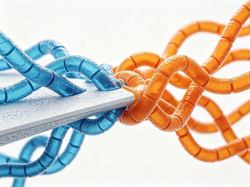
Chemical Adhesion and Molecular Entanglement
Chemical bonding occurs at the interface of the two resins during the molding process. For a true chemical bond to take place, the overmold material must have sufficient thermal energy to slightly melt the surface layer of the substrate. This allows the polymer chains of both resins to interdiffuse, entangle, and co-crystallize as they cool. This molecular entanglement creates a permanent bond that resists peeling and delamination. Chemical affinity requires compatible materials; generally, polar polymers bond best with polar polymers, while non-polar materials require specific modification. For example, standard thermoplastic elastomers (TPE) and thermoplastic vulcanizates (TPV/Santoprene) bond well to polyolefins like polypropylene (PP), but exhibit poor adhesion to engineering plastics like polycarbonate (PC) or ABS unless chemically modified. A TPE formulated to bond to Nylon will not necessarily adhere to PC, making grade-specific selection paramount.
Mechanical Bonding and Low Surface Energy Plastics
Some plastics possess low surface energy, which makes them highly resistant to chemical bonding. Materials like polyoxymethylene (POM/Acetal), high-density polyethylene (HDPE), and polypropylene (PP) are chemically stable and slippery, preventing molecular entanglement with standard overmolds. When these materials must be used, or when bonding silicone rubber to non-silicone polymers, engineers rely on mechanical bonding. This involves designing physical retention features directly into the substrate. By incorporating undercuts, reverse-tapered holes, dovetail slots, or through-holes with counterbores, the molten overmold material flows into the substrate and locks itself in place once solidified. The tear resistance of the overmold material then becomes the limiting factor for bond strength, ensuring a durable, reliable connection.
When overmolding metal inserts, achieving a strong bond presents unique challenges because metals do not melt or chemically react with standard overmold resins. To overcome this, we rely heavily on mechanical retention. Designing the metal insert with specialized features like knurling, grooves, flanges, or undercuts allows the plastic to flow into these areas and lock the insert in place. Additionally, specialized chemical primers or heat-activated adhesives can be applied to the metal surface before molding to form a reliable chemical bridge. In some advanced configurations, direct bonding of certain resins to metal requires an intermediate “tie-layer.” For example, standard thermoplastic polyurethane (TPU) will not bond directly to stainless steel. To solve this, our engineering team first molds a thin layer of Polypropylene (PP) onto the metal insert, and then overmolds the TPU onto the PP substrate. This intermediate tie-layer resolves the compatibility issue and prevents peeling under heavy mechanical stress.
For highly demanding industrial and electronic applications, we also work with high-performance thermoset molding compounds. Materials such as Diallyl Phthalate (DAP), phenolics, and glass-filled Sheet Molding Compounds (SMC) or Bulk Molding Compounds (BMC) provide exceptional dielectric strength, dimensional stability, and resistance to elevated temperatures. These materials chemically cure during the molding process, forming cross-linked polymer networks that do not melt when reheated. When insert-molding electrical pins or structural mounts into these thermoset resins, the result is an incredibly strong, heat-resistant assembly. For specialized semiconductor and chemical processing equipment, we also mold fluoropolymers like FEP and PFA. These materials are chemically inert and can withstand highly corrosive environments, but they have exceptionally high melt temperatures and narrow processing windows. Managing these advanced resins requires specialized tooling steels and precise process control to prevent off-gassing corrosion and maintain part tolerances.
| Substrate Polymer (1st Shot) | Overmold Elastomer (2nd Shot) | Bonding Classification | DFM Recommendations |
|---|---|---|---|
| ABS / Polycarbonate (PC) | TPE / TPU / PC / PMMA | Chemical (Covalent Fusion) | Ensure clean surface, keep overmold temp high |
| Nylon (PA6 / PA66) | TPU / TPE / Santoprene | Chemical (High-Affinity) | Preheat substrate for manual insert molding |
| Polypropylene (PP) | Olefinic TPE / TPV (Santoprene) | Chemical (Grafted Affinity) | Requires specific polyolefin-compatible grades |
| Polyacetal (POM / Acetal) | TPE / TPU | Mechanical (Zero Chemical Bond) | Incorporate dovetail undercuts & slots |
| Glass-Filled Polymers | Silicone (LSR) / TPE | Mechanical / Chemical | Requires surface activation or texturing |
| Metals (Brass, Steel) | Silicone (LSR) / Thermoplastics | Mechanical (Locking Features) | Apply knurling, counterbores, or primers |
4. Design for Manufacturability (DFM) Guidelines
Designing a part for overmolding is more complex than standard injection molding. Because you are molding a secondary hot polymer over a solidified substrate, you must balance thermal expansion, material shrinkage, and injection pressures. Following robust Design for Manufacturability (DFM) guidelines during the CAD phase is the best strategy to prevent common injection molding flaws and ensure excellent quality.
Wall Thickness Uniformity and Flow Limits
Like any plastic injection molded part, maintaining a consistent wall thickness throughout both the substrate and the overmold is critical. Consistent thickness promotes even material flow and balanced cooling, preventing sink marks, voids, and warping. The substrate wall should be thick enough (typically 1.5mm to 3.0mm) to withstand high injection pressures without collapsing or deforming. The overmold wall thickness should ideally range from 1.0mm to 2.5mm, with 1.5mm as a recommended nominal baseline. If the overmold is too thin (less than 1.0mm), the material can freeze off prematurely, resulting in incomplete fills. To ensure complete material flow, keep the overmold flow-length-to-thickness ratio under 150:1 (ideally target 80:1 for detailed geometries).
Draft Angles and Mold Ejection
Draft angles—the slight taper applied to vertical surfaces—are essential to ensure that the completed part can be easily ejected from the mold tool without scratching or tearing. The substrate requires standard draft angles of 1.5° to 3.0°. However, soft elastomer overmold materials (like TPE or TPU) have a high tendency to cling and stick to polished tool steel. For overmolded areas, we recommend draft angles of 2° to 5° for smooth surfaces, and up to 5° to 7° for textured surfaces or deep structural ribs. This prevents the elastomer from tearing or pulling away from the substrate during mold opening.
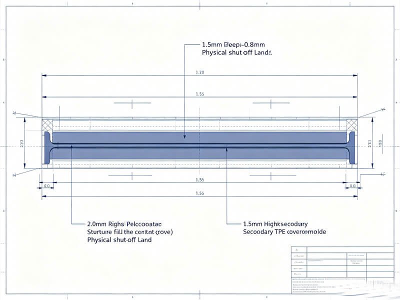
Shut-Off Design and Accent Grooves
A shut-off is any area where the steel mold halves press and seal tightly against the pre-molded substrate to prevent the secondary material from leaking (flashing). To maintain clean cosmetic edges, you must avoid shutting off on vertical or inclined surfaces over 45°. The sealing surface (land) should be at least 1.2mm wide and perpendicular to the parting line. To prevent thin, feathered overmold areas that easily peel or delaminate, incorporate a physical “step” or an accent groove (1.5 mm to 2.0 mm deep, and 0.8 mm to 1.0 mm wide) along the boundary lines on the substrate. This step provides a secure, flat surface for the mold steel to compress against, creating a crisp, flash-free, and professional edge.
When designing these sealing boundaries, the complexity of the part geometry will dictate the necessary shut-off features. For flat, straightforward sealing paths, a flat sealant land of 1.2mm is standard. However, where the sealing path is complex or involves steep angles, the sealant land width should be increased to 1.8mm. Any bevels along the shut-off edge must not exceed 45 degrees to ensure the mold steel can compress safely against the substrate. Furthermore, if you are incorporating locator pins or structural ribs near the sealing boundary, you must keep them at least 1.0mm away from the shut-off line. For high-volume tools, we often design small “nail holes” or shut-off pins spaced 20mm to 30mm apart near the boundary edges. These pins hold the substrate securely and prevent high-pressure molten plastic from overflowing into adjacent structural rib gaps, which would otherwise result in glue leakage or cosmetic burrs.
Gate Location and Vestige Management
The gate is the channel through which molten plastic enters the mold cavity. When the material solidifies and the gate is sheared, a small blemish known as gate vestige is left behind. To ensure clean cosmetics, position the first-shot gate in an area that will be completely covered by the second-shot overmold. For the overmold itself, place gates in the thickest section of the part to ensure uniform packing and reduce flow length. Edge gates provide excellent material flow and help form strong bonds. If the overmolded area is in an inaccessible location, we can utilize sub-gates (subgating from the core) or design internal transfer holes within the substrate to channel the overmold material where it is needed.
It is also helpful to distinguish between different gate types. While simple tab gates are common and cost-effective, they always leave a noticeable vestige on the part surface that may require manual post-mold trimming. For high-cosmetic consumer electronics, we recommend hot tip gates. These systems utilize a thermostat-controlled heater attached to the back of the mold to keep the polymer in a molten state up to the gate drop. This allows the material to pass through an extremely small, clean gate hole, eliminating manual degating and leaving an almost invisible gate mark. Furthermore, the gate should be oriented so that the material flows smoothly around any metal inserts or vertical ribs. This prevents the formation of structural weld lines (the boundary where two flow fronts meet) in high-stress areas of the part, ensuring maximum impact strength.
| Design Feature | Standard Recommended Value | Operational Engineering Purpose |
|---|---|---|
| Substrate Wall Thickness | 1.5mm – 3.0mm | Provides rigidity, resists injection pressure & warping |
| Overmold Wall Thickness | 1.0mm – 2.5mm (1.5mm nominal) | Ensures smooth material flow, prevents premature freezing |
| Draft Angle (Substrate) | 1.5° – 3.0° | Ensures clean ejection of the base part from Mold A |
| Draft Angle (Overmold) | 2.0° – 5.0° (Up to 7.0° for textures) | Prevents sticky soft elastomer from tearing during mold open |
| Accent Groove Dimensions | 1.5mm – 2.0mm deep, 0.8mm – 1.0mm wide | Provides secure shut-off area, prevents bleeding and flash |
| Max Flow-Length Ratio | < 150:1 (Ideally 80:1) | Ensures complete filling of the overmold cavity |
5. Common Defects and Process Control
Advanced overmolding requires tight process control and highly precise tooling. Because you are combining multiple materials under high heat and pressure, even minor deviations can lead to high-cost defects and increased scrap rates. Understanding the root causes of common overmolding defects and implementing rigorous process controls at the factory level is essential to ensure consistent quality.
Critical Defects and Remediation
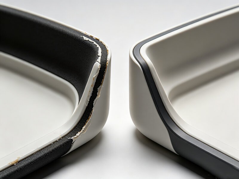
- Delamination (Peeling / Debonding): This occurs when the overmold material lifts or separates from the substrate. This is typically caused by surface contamination (such as moisture, oil, or dust) on the substrate, low injection temperatures, or material incompatibility. To resolve this, keep the substrate surfaces dry and clean, elevate the overmold melt temperature to its upper recommended limits, and preheat the substrate before the second injection.
- Flash and Bleeding: Molten overmold material leaks past the shut-off surfaces, leaving thin, excess plastic along the parting line. This is caused by inadequate mold clamping pressure, high injection pressure, or feathered shut-off designs. Remediation involves increasing the machine clamp force, reducing injection velocity, and designing hard steps or accent grooves rather than thin, tapered profiles.
- Warping and Shrinkage: The part twists or distorts during cooling. This occurs when the substrate and overmold materials have mismatched coefficients of thermal expansion (CTE) or uneven cooling rates. To manage this, choose materials with compatible shrink rates, balance the cooling channels within both molds, and extend the overmold cooling cycle time so the part solidifies under consistent thermal conditions.
- Substrate Melting (Erosion): The substrate softens, deforms, or melts under the high heat and pressure of the secondary injection. This occurs when the overmold melt temperature exceeds the substrate’s heat deflection temperature (HDT), or when gates are placed directly opposite thin substrate walls. To prevent this, reduce the overmold injection speed, lower the melt temperature within safe processing limits, or select a substrate polymer with a higher thermal processing window.
Rigorous Factory Process Control Guidelines
To guarantee the structural integrity of every part, our partners at RapidAPlus strictly enforce these processing protocols on the production floor:
- Complete Moisture Control: Both the substrate and overmold raw materials must be thoroughly dried to the resin manufacturer’s exact specifications. Moisture in the material can lead to foaming, splay, and poor bonding.
- Prohibit Mold Release Sprays: Standard silicone or wax-based mold release sprays are a cardinal sin in overmolding. They leave a thin, slippery film on the substrate, completely preventing chemical adhesion and causing immediate delamination.
- Maximize Injection Velocity and Pressure: Use the highest possible injection speed and pressure during the overmold shot. This encourages rapid cavity filling before the elastomer can freeze off, promoting intimate contact and maximum molecular chain entanglement at the interface.
- Substrate Preheating: For manual pick-and-place overmolding, preheating the substrate before loading it into the overmolding mold brings its surface temperature closer to the melt temperature of the overmold, significantly increasing chemical bond strength.
6. Overmolding for Prototyping and Low-Volume Runs
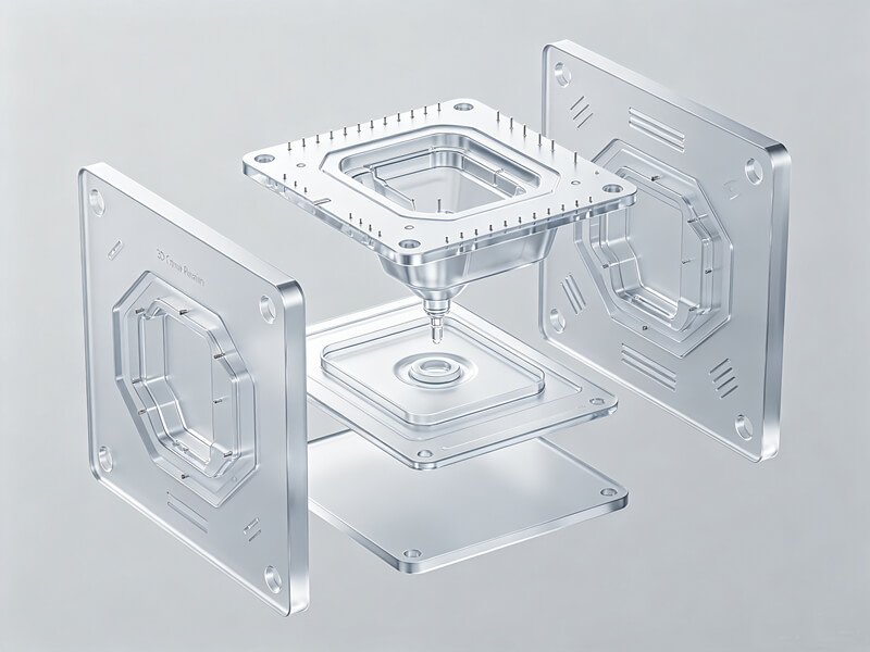
Historically, overmolding was considered too expensive for prototypes and short production runs because of the high cost of double-shot steel tooling. However, the rise of advanced rapid tooling techniques has changed this dynamic. By combining Stereolithography (SLA) 3D printing with manual overmolding, product development teams can now produce functional, multi-material prototypes quickly and at a fraction of the cost of traditional tooling.
Rapid Tooling via SLA 3D Printing
Using high-resolution SLA 3D printers, designers can print mold inserts using materials like Clear Resin. Clear Resin is highly recommended because its transparent finish allows operators to visually monitor the material flow and verify that internal inserts are aligned correctly. Printing with a 50 μm layer height provides an excellent balance between a smooth surface finish and fast printing times. It is critical to orient the mold on the build plate so that critical interior surfaces are free from support marks. Once printed, the molds are washed thoroughly in Isopropyl Alcohol (IPA) to ensure no uncured resin remains, as residual liquid can inhibit the curing chemistry of cast silicones or elastomers. After washing, the molds are post-cured at 60°C for 15 minutes.
Step-by-Step RTV Silicone Overmolding Protocol
To encapsulate internal hardware or add a soft-touch rubber sheath to a prototype, follow this established rapid overmolding procedure:
- Silicone Preparation: Use a two-part, medical-grade RTV liquid silicone (a durometer of 20-40 Shore A is recommended). Fill an empty epoxy cartridge with Part A and Part B using separate syringes. Stand the cartridge upright and allow it to degas for at least 1 hour to 1 day to eliminate air bubbles. Add silicone dye to either side and mix thoroughly if color is required.
- Insert Positioning: Place your preformed substrate (such as a metal insert, circuit board, or rigid plastic core) into the mold cavity. Utilize built-in 0.2mm diameter alignment pins in the mold to constrain and support the substrate, setting a minimum overmold thickness of 1.5mm to 2.0mm.
- Mold Clamping and Sealing: Close the mold and compress it by hand. Seal the external parting lines with duct tape to reduce material leakage and flashing. Clamp the mold halves tightly using C-clamps applied perpendicular to the main parting line.
- Silicone Injection: Insert the mixing nozzle of the epoxy gun into the mold inlet. Squeeze the trigger gently, watching the silicone flow through the transparent Clear Resin mold. Continue injecting until the cavity is full and silicone emerges from all air vents. Hold a handheld sander or vibrating device against the mold to encourage any trapped air bubbles to rise and vent.
- Demolding and Trimming: Allow the silicone to cure fully according to the manufacturer’s directions. Carefully cut any excess silicone off the mold exterior before opening. Gently pry the mold halves apart using a spatula. Take your time near the air vents, as the cured silicone in the vents can tear the soft-touch surface of your part if yanked. Use flush cutters or a sharp blade to trim away any residual flashing.
7. Specialized Industry Applications
The functional and aesthetic benefits of overmolding make it an essential technology across modern manufacturing. From reducing part count to enhancing durability, this versatile process is utilized in several of the most demanding global industries.
Medical Device Manufacturing
In healthcare and medical diagnostics, overmolding is highly valued for its ability to combine comfort with sterility. Surgical instruments require soft, non-slip handles that provide surgeons with precise control during delicate procedures, yet must also survive repeated, high-temperature steam autoclave sterilizations. By overmolding medical-grade liquid silicone rubber (LSR) or specialized elastomers over rigid PEEK or Ultem cores, manufacturers can create durable, biocompatible, and ergonomically superior tools. Additionally, overmolding is used to encapsulate delicate electronic sensors, pacemakers, and blood glucose monitors inside protective, fluid-resistant, and sterilizable plastic shells, ensuring safety and performance inside the human body.
To understand how custom insert molding solves critical healthcare challenges, let us look at a real-world case study. In 1983, a medical device project was initiated to design a new multi-lumen heart catheter. At the time, all catheters were hand-assembled using liquid adhesives—a slow, inefficient process that utilized hazardous chemicals and resulted in high product rejection rates due to adhesive leakage. Our engineers developed an alternative insert-molded solution. We placed stainless steel mandrels directly through each polyurethane extension tube and aligned them within a multi-lumen extrusion. Polyurethane was then insert-molded into a manifold around the assembly. After molding, the mandrels were removed, leaving reliably aligned, open passageways.
The initial challenge with this design was ensuring that the adjacent internal channels did not touch or cross paths during high-pressure molding, which would cause catastrophic leakage during a surgical procedure. The first prototype used a flat “Y” shaped manifold, which made it extremely difficult to prevent the mandrels from shifting and touching. To solve this, our technical team redesigned the manifold to separate the extension lumens into a precise circular pattern. This circular layout provided ample space between the mandrels, keeping them perfectly isolated during the injection cycle. This successful design remains the manufacturing standard today for all catheter assemblies with more than three lumens, proving how precise tooling and DFM engineering protect patient safety and improve production yields.
Automotive Industry Systems
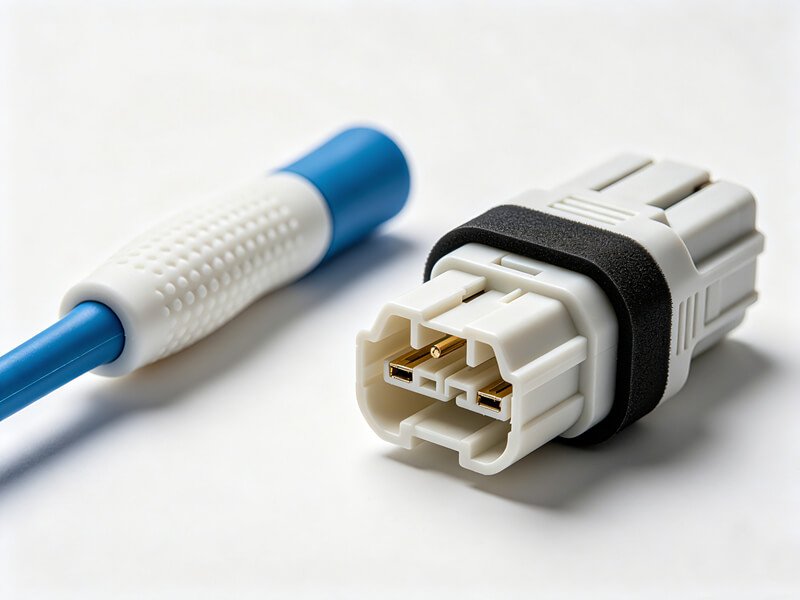
Automotive OEMs rely on overmolding to improve cabin comfort, seal electrical systems, and reduce vehicle weight. Interior door panels, dashboard knobs, steering wheels, and shift levers utilize soft-touch overmolding to create a premium tactile experience for drivers. Under the hood, where components are subjected to extreme heat, vibration, and fluid exposure, overmolding is used to create airtight and watertight seals on electrical connectors and sensor housings. This eliminates the need for separate gaskets, reducing assembly steps and preventing joint failures. Fluid reservoirs and anti-vibration rubber mounts are also overmolded directly onto structural metal brackets to save space and reduce weight.
Consumer Electronics and Industrial Tools
In consumer tech, overmolding is a vital tool for environmental protection and haptic appeal. Outdoor Bluetooth speakers, smartwatches, and fitness trackers utilize overmolded elastomer layers to achieve high water-resistance (IP67/IP68) ratings without separate rubber gaskets. Protective phone cases combine a rigid polycarbonate shell with a shock-absorbing TPU overmold to protect delicate internal screens from drop impact. Similarly, in the industrial sector, hand tools such as screwdrivers, pliers, and power drills utilize durable, chemical-resistant soft-grip overmolds. This provides secure, non-slip handling in wet or oily conditions, while absorbing mechanical vibrations to reduce operator fatigue.
8. FAQ
9. Conclusion and Light Recommendation
In summary, overmolding is an advanced injection molding technique that allows product developers to combine different material properties, colors, and textures into a single, cohesive component. By eliminating manual assembly, reducing post-molding operations, and providing durable molecular bonds, overmolding improves part durability, user ergonomics, and structural performance. However, achieving consistent quality requires careful material selection, precise shut-off design, and tight process controls.
If you are developing a product that requires multi-material capabilities, early engineering support is the best way to optimize your tool design and material choices. At RapidAPlus, our experienced team of design engineers, mold makers, and process technicians works closely with you through every step of the development cycle—from design for manufacturability (DFM) and rapid prototyping to full-scale automated production. We help you choose the most efficient process, navigate complex polymer pairings, and deliver high-quality, reliable components to market quickly.